F4LW Hardware
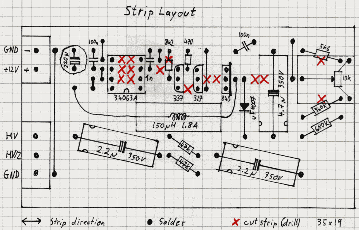
There's currently no PCB for the F4LW, all circuits have been built on simple strip boards. However, below I included the strip board layout, if you want to build a F4LW yourself. Each main component has been built on its own strip board, the boards are connected with plugs and sockets.
The tubes are multiplexed and data from the MCU board is transferred serially to the DDU board, so 4 data wires (+ 4 power wires) suffice.
Please note, that I'm a novice in designing electronic circuits, so I based F4LW hardware mainly on the PENTA design.
Be careful, F4LW operates with high voltage upto 190V, so don't touch any of the boards while power is on and wait at least 5 seconds after powering off before you touch it!
Remote control
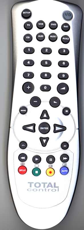
The F4LW is mainly controlled via an infrared RC-5 remote control. I used a URC 2082, which is available at Conrad Elektronik (article nr. 340720 - 62) in Germany for about 10 €, but any RC-5 remote control will work if you change the corresponding PIC include files.
The URC 2082 is set to code 0579, where unique RC-5 codes
for each button are sent.
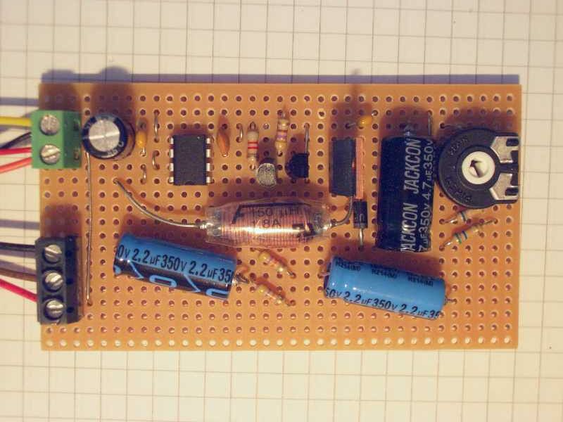
High voltage power supply
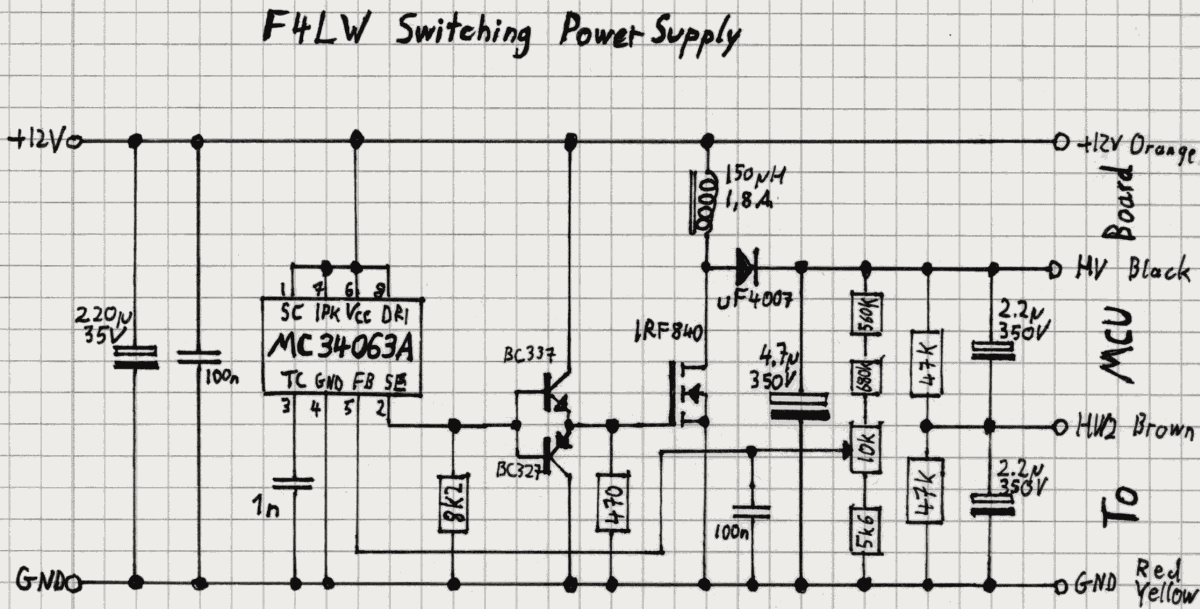
This is a fairly standard design taken from the NEONIXIE circuit archive using the MC34063 controller. It provides adjustable high voltage of about 170-190V. I use a 12V DC "wall-wart" power supply, so no rectifier is needed. You can even run F4LW from a 9V block battery!
Use the poti to adjust the output voltage to 175-185V.
| Schematic | Strip layout | Board picture |
|---|---|---|
| 
| 
|
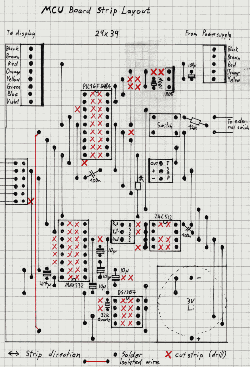
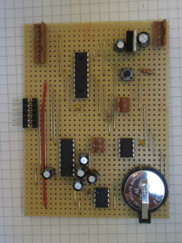
Microcontroller board
This board contains a PIC 16F648A microcontroller, a DS1307 real-time clock, a 24C512 serial EEPROM and a MAX232 serial driver. There are also several connection sockets for the TSOP 1736 infrared receiver, the RS232 socket, a single mechanical switch, and the ICSP port.
The serial EEPROM and the real-time clock are connected to the PIC via an I2C bus. Since the PIC doesn't have I2C hardware support, the I2C bus is emulated in software. The bidirectional SDA signal is connected to 2 IO pins, where one pin is permanently set to input and the other to output.
| Schematic | Strip layout | Board picture |
|---|---|---|

| 
| 
|
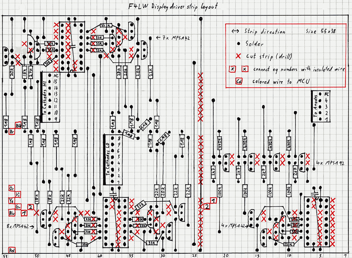
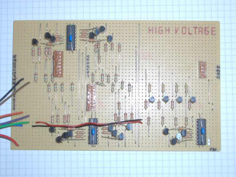
Display driver board
A lot of MPSA42/92 transistors and even more resistors! I used the HV/2 technique (a high-valued resistor from each anode and cathode to middle potential) here to achieve a faster response to voltage changes to avoid lighting segments spuriously.
Multiplexing is obtained with only 3 4094 (8 bit shift registers). Two of them are wired to 15 cathode-driving MPSA42. The other 4094 drives the anodes, it could handle up to 8 tubes but here it drives only 4. A total of 19 MPSA42 and 4 MPSA92 is needed, together with the proper number of resistors. The trade-off for component reduction is in the increase in software complexity, but not much, after all.
There is one 4094 8 bit shift register that accepts data concerning which of the 4 tubes should be turned on, by applying high voltage to its anode. Here only 4 bits are used.
There are two 4094 8 bit shift registers that receive a total of 16 bits coding for the segments to be turned on, by pulling the corresponding cathodes to ground through the proper cathode-associated drivers. The DATA line of the "anode section" 4094 and the DATA line of the first 4094 of the "cathode section" are connected together and to RA0. Bits shifted out of the first 4094 are shifted into the next one.
By software, a stream of 16 bits coding for the segments to be turned on is sent by the PIC to the DATA line, properly clocked on the CLOCK line (which is common to all 4094). The 16 bits will shift into the cathodes' 4094 and align properly. (Only 15 bits are used here, since the 7971 tubes have no decimal point like the ZM1350 Giampaolo used) The bits will also shift into the anodes' 4094, however, it will not store the cathode bits because a STROBE-CATHODES signal will only be applied to the strobe lines of cathodes' 4094s connected in parallel to RA1.
Immediately after this, a 8 bit stream is sent, carrying the information on which display has to be turned ON. Similar to above, STROBE-ANODES ensures that only the anodes' bit will be changed and the cathodes' data is left intact.
This very elegant design (and also the description above) is from Giampaolo Minetti's PENTA.
| Schematic | Strip layout | Board picture |
|---|---|---|

| 
| 
|
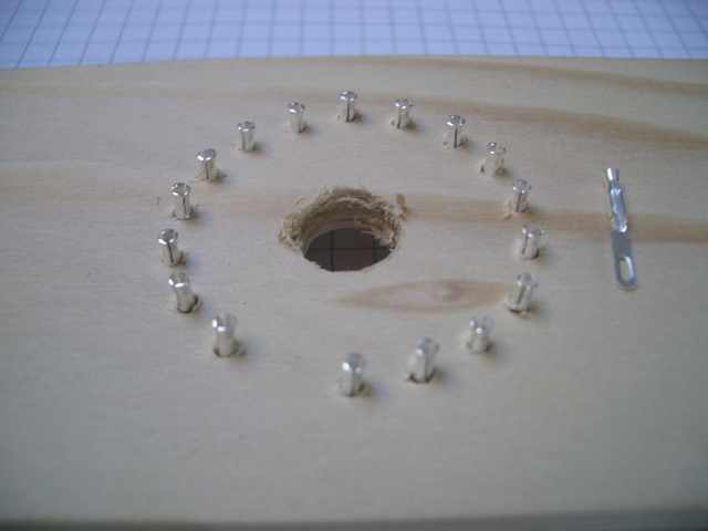
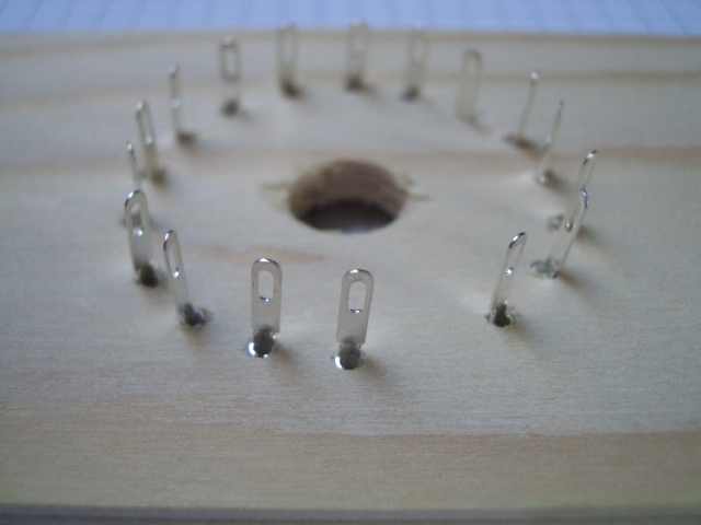
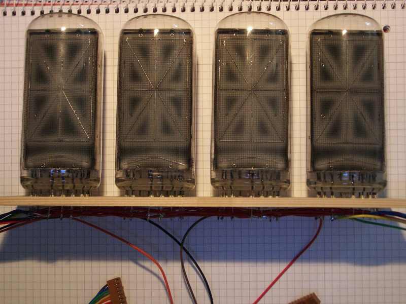
Tube socket board
Unfortunately, sockets for B7971 tubes are hardly available nowadays, so I had to build them myself. It's a simple wooden board where holes for each tube pin were drilled and single pin sockets were inserted and connected by soldering at the backside.
The holes measure 2mm in diameter and the board is 5mm thick. The sockets are not glued to the board, but inserting the carefully straighted pins of the 7971 tubes keep them fixed. You must hold a solid surface against the sockets from below when inserting the tubes, so that the sockets are not pushed out of their holes. Unplugging a tube is easier, the solder lug prevents the socket from being drawn through the hole.
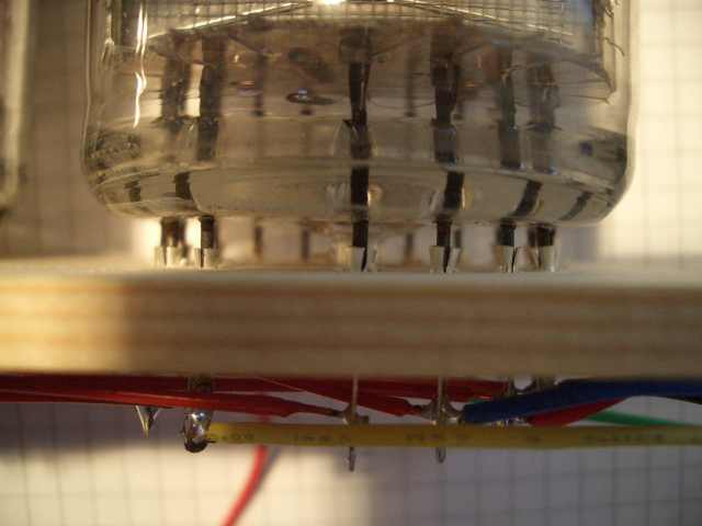
At the bottom side of the board, same-numbered cathodes are connected with insulated wire and soldered to two 8 wire plugs (only 7 are used for the HI segments), which are plugged into the 2 cathodes sockets on the DDU board.
The anodes (pin 13) are not connected, of course, but soldered separately to the wires leading to the anodes plug, which goes into the anodes socket on the DDU board.

| 
| 
|
| 
| 
|
Altogether
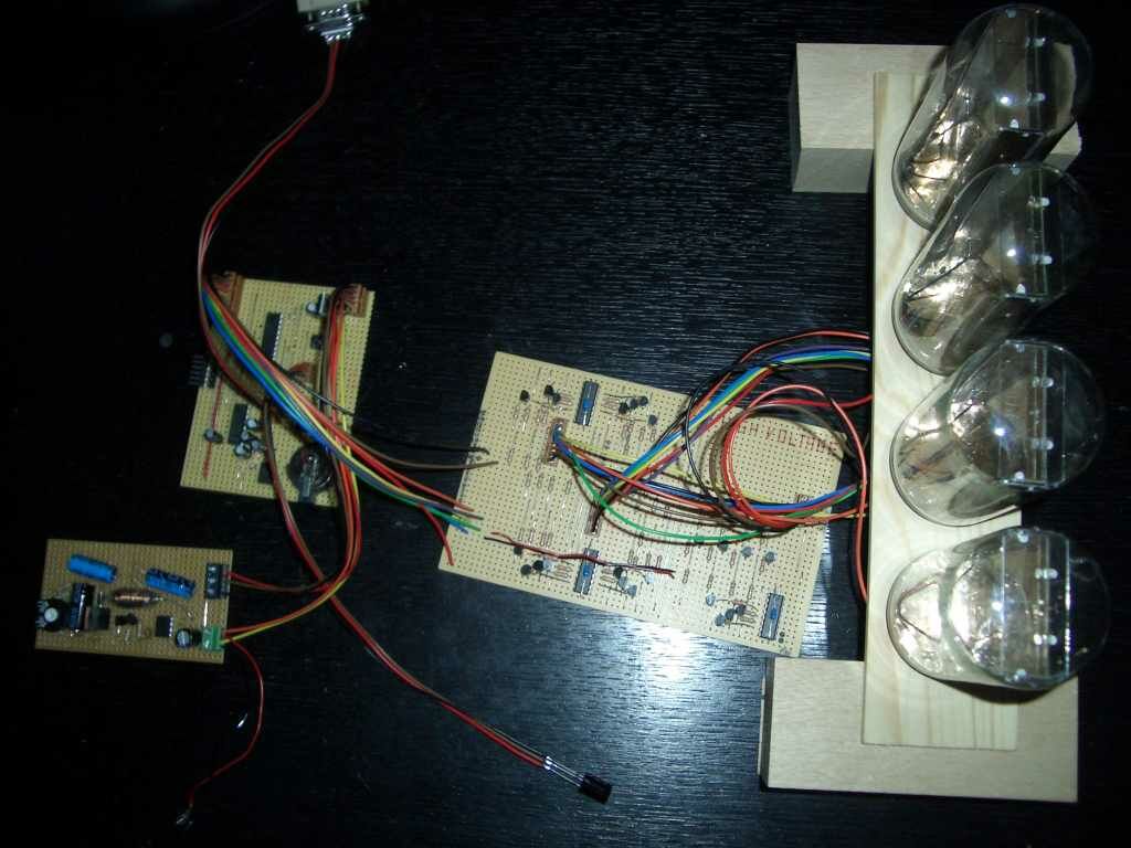
All components mentioned above have been connected with simple wires, plugs and sockets.
Of course, a lot of connectors could have been spared by placing everything on the same PCB, but since my F4LW is probably the only exemplar ever to be built, putting the prototype to production was the easiest way :-)